การอ่านค่ารีโมท Receiver 4,6,8 CH
การอ่านและแปลงค่าสัญญาณพัลส์จากรีโมทเครื่องบินบังคับ RC
,Futaba, stom i6, FlySky FS-i6 2.4G 6CH ,FlySky TH9x, 9XR,
https://github.com/QuadTinnakon/Read_Receiver
ตัวอย่างโค๊ต
/*
project__2560 Read Receiver 4,6,8 CH
by: tinnakon kheowree
tinnakon_za@hotmail.com
tinnakonza@gmail.com
http://quad3d-tin.lnwshop.com/
https://www.facebook.com/tinnakonza
date: 22-01-2558(2015) V.1 ReadRCn_2560Pk_V1.ino
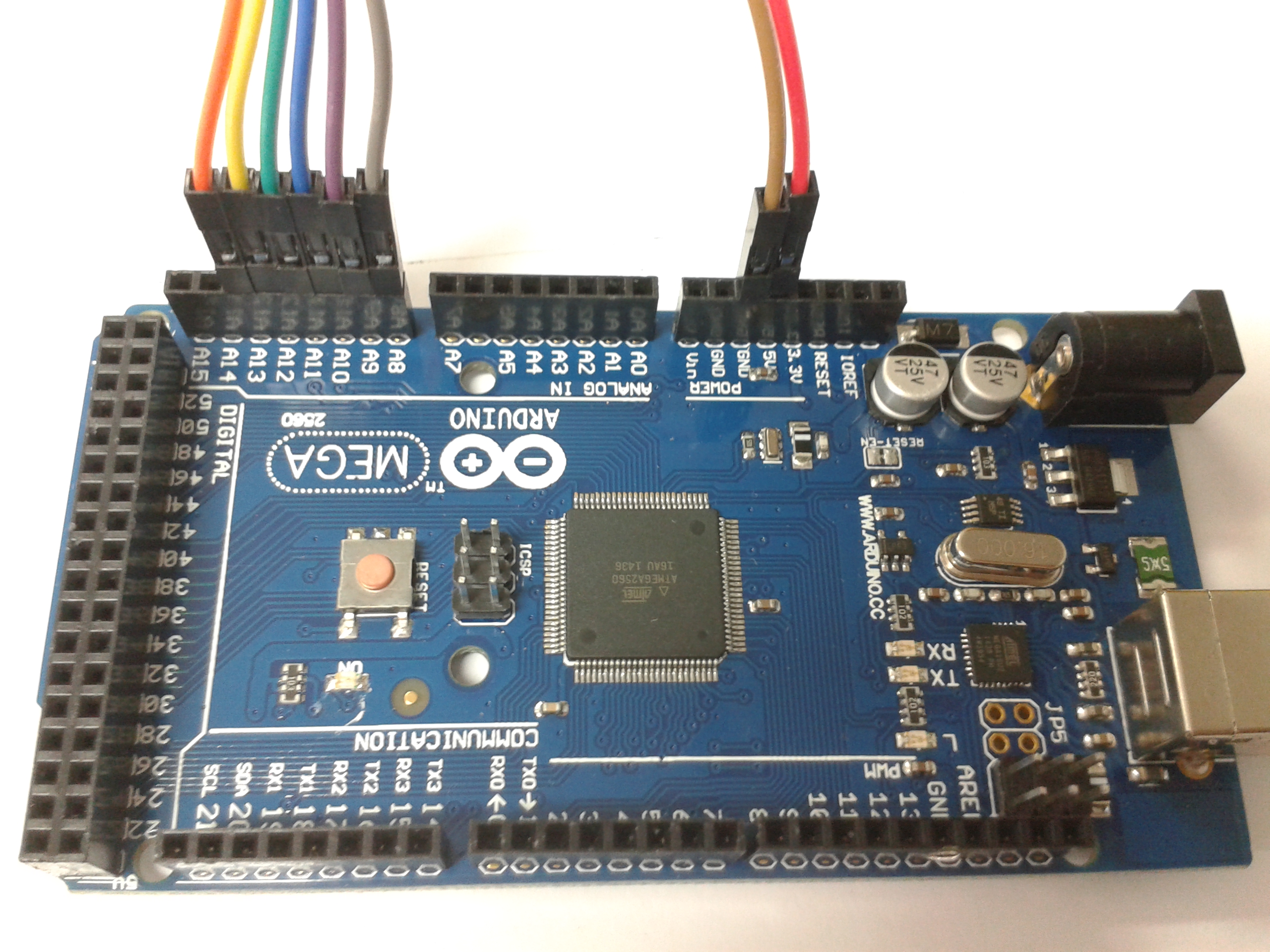
support: Board 2560
• Atmega2560
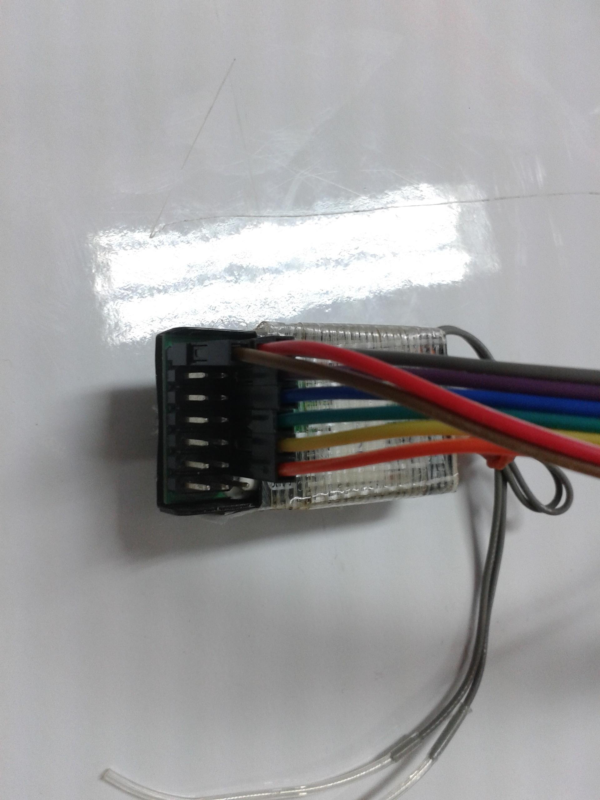
• RC Receiver 4,6,8 CH ,Futaba, stom i6, FlySky FS-i6 2.4G 6CH
,FlySky TH9x, 9XR,
----------rx-----------
PORTK
#define THROTTLEPIN 1 //PIN 62 = PIN A10
#define ROLLPIN 2 //PIN 63 = PIN A8
#define PITCHPIN 0 //PIN 64 = PIN A9
#define YAWPIN 3 //PIN 65 = PIN A11
#define AUX1PIN 4 //PIN 66 = PIN A12
#define AUX2PIN 5 //PIN 67 = PIN A13
#define AUX3PIN 6 //PIN 68 = PIN A14
#define AUX4PIN 7 //PIN 69 = PIN A15
*/
#include
#include "config.h"
#include "multi_rx2560.h"
void setup()
{
Serial.begin(57600);//38400
pinMode(13, OUTPUT);pinMode (30, OUTPUT);pinMode (31, OUTPUT);//pinMode (30, OUTPUT);pinMode (31, OUTPUT);//(13=A=M),(31=B=STABLEPIN),(30=C,GPS FIG LEDPIN)
digitalWrite(13, HIGH);
//Serial1.begin(115200);//CRIUS Bluetooth Module pin code 0000
//Serial3.begin(38400);//3DR Radio Telemetry Kit 433Mhz
configureReceiver();//find multi_rx.h
delay(1000);
RC_Calibrate();//"multi_rxPPM2560.h"
Serial.print("TK_Quadrotor_Read Receiver");Serial.println("\t");
previousTime = micros();
}
void loop()
{
Dt_roop = micros() - previousTime;// 100 Hz task loop (10 ms) , 5000 = 0.02626 ms
if(Dt_roop <= 0)
{
Dt_roop = 10001;
}
if (Dt_roop >= 10000)
{
previousTime = micros();
G_Dt = Dt_roop*0.000001;
frameCounter++;
if (frameCounter % TASK_50HZ == 0)// 50 Hz tak (20 ms)
{
computeRC();//multi_rx.h
//failsafeCnt++;
//Fail_Safe();
}//end roop 50 Hz
if (frameCounter % TASK_20HZ == 0)//roop print ,TASK_5HZ TASK_10HZ
{
Serial.print(CH_THR);Serial.print("\t");
Serial.print(CH_AIL);Serial.print("\t");
Serial.print(CH_ELE);Serial.print("\t");
Serial.print(CH_RUD);Serial.print("\t");
Serial.print(AUX_1);Serial.print("\t");
Serial.print(AUX_2);Serial.print("\t");
Serial.print(AUX_3);Serial.print("\t");
Serial.print(AUX_4);Serial.print("\t");
//Serial.print(failsafeCnt);Serial.print("\t");
//Serial.print(CH_AILf);Serial.print("\t");
//Serial.print(CH_ELEf);Serial.print("\t");
//Serial.print(CH_RUDf);Serial.print("\t");
Serial.print(G_Dt*1000);Serial.print("\t");
//Serial.print(millis()/1000.0);//millis() micros()
Serial.print("\n");
}//end roop 5 Hz
if (frameCounter >= TASK_1HZ) { // Reset frameCounter back to 0 after reaching 100 (1s)
frameCounter = 0;
//time_auto++;
//Remote_TrimACC();//motor.h
if(Status_LED == LOW)
{
Status_LED = HIGH;
}
else
{
Status_LED = LOW;
}
digitalWrite(13, Status_LED);//A
}//end roop 1 Hz
}//end roop 100 HZ
}
้ไฟล์ config.h
/*
project_2560 Read Receiver 4,6,8 CH
support: Board 2560
• Atmega2560
• RC Receiver 4,6,8 CH ,Futaba, stom i6, FlySky FS-i6 2.4G 6CH
,FlySky TH9x, 9XR,
by: tinnakon kheowree
tinnakon_za@hotmail.com
tinnakonza@gmail.com
http://quad3d-tin.lnwshop.com/
https://www.facebook.com/tinnakonza
*/
//The type of multicopter
//#define Quad_X
#define PPM
///////////////Mode///////////////////////////
#define AltHold 1500
#define PositionHold 1700
#define Auto 1960
int Mode = 0;
//Mode 0 = Stabilize
//Mode 1 = Altitude Hold
//Mode 2 = Position Hold ,Loiter
//Mode 3 = Automatic Takeoff ,Landing
#define MINTHROTTLE 1064 //1090
#define MAXTHROTTLE 1850
#define MINCOMMAND 1064
#define MAXCOMMAND 1850
#define MIDRC 1500
#define MINCHECK 1100
#define MAXCHECK 1900
/////////////////////////////////////////////
/////////////////////////////////////////////////////////////////////
// Automatic take-off and landing
#define h_control 0.9 //0.6 0.9 meter
//////////////////////////////////////////////////////////////////////
//////////////////RC//////////////////////////////////
//#define tarremote 0.025 // fast
#define tarremote 0.025 //0.092 slow 0.12 0.02 0.08 remote
#define tar 0.015 //0.011 0.012 0.015
//////////////////////////////////////////////////
#define TASK_100HZ 1
#define TASK_50HZ 2
#define TASK_20HZ 5
#define TASK_10HZ 10
#define TASK_5HZ 20
#define TASK_2HZ 50
#define TASK_1HZ 100
#define RAD_TO_DEG 57.295779513082320876798154814105
float cos_rollcos_pitch = 1.0;
// Main loop variables
unsigned long currentTime = 0;
unsigned long previousTime = 0;
unsigned long sensorPreviousTime = 0;
uint8_t frameCounter = 0;
uint8_t timeLanding = 0;
uint8_t timeOff = 0;
byte armed = 0;
float G_Dt = 0.01;
long Dt_sensor = 1000;
long Dt_roop = 10000;
int Status_LED = LOW;
int ESC_calibra = 0;
ไฟล์ multi_rx2560.h
/*
project_2560 Read Receiver 4,6,8 CH
support: Board 2560
• Atmega2560
• RC Receiver 4,6,8 CH ,Futaba, stom i6, FlySky FS-i6 2.4G 6CH
,FlySky TH9x, 9XR,
by: tinnakon kheowree
tinnakon_za@hotmail.com
tinnakonza@gmail.com
http://quad3d-tin.lnwshop.com/
https://www.facebook.com/tinnakonza
*/
int CH_THR = 1000;
int CH_AIL = 1500;
int CH_ELE = 1500;
int CH_RUD = 1500;
float CH_AILf = 1500;
float CH_ELEf = 1500;
float CH_RUDf = 1500;
int CH_AIL_Cal = 1500;
int CH_ELE_Cal = 1500;
int CH_RUD_Cal = 1500;
int AUX_1 = 1500;
int AUX_2 = 1500;
int AUX_3 = 1500;
int AUX_4 = 1500;
int roll_mid = 1475;
int pitch_mid = 1479;
int yaw_mid = 1474;
//RX PIN assignment inside the port //for PORTK
#define THROTTLEPIN 1 //PIN 62 = PIN A8
#define ROLLPIN 2 //PIN 63 = PIN A9
#define PITCHPIN 0 //PIN 64 = PIN A10
#define YAWPIN 3 //PIN 65 = PIN A11
#define AUX1PIN 4 //PIN 66 = PIN A12
#define AUX2PIN 5 //PIN 67 = PIN A13
#define AUX3PIN 6 //PIN 68 = PIN A14
#define AUX4PIN 7 //PIN 69 = PIN A15
#define PCINT_PIN_COUNT 8
#define PCINT_RX_BITS (1<<2),(1<<4),(1<<5),(1<<6),(1<<7),(1<<0),(1<<1),(1<<3)
#define PCINT_RX_PORT PORTK
#define PCINT_RX_MASK PCMSK2
#define PCIR_PORT_BIT (1<<2)
#define RX_PC_INTERRUPT PCINT2_vect
#define RX_PCINT_PIN_PORT PINK
#define RC_CHANS 8 //read Ch
static uint8_t PCInt_RX_Pins[PCINT_PIN_COUNT] = {PCINT_RX_BITS}; // if this slowes the PCINT readings we can switch to a define for each pcint bit
volatile uint16_t rcValue[RC_CHANS] = {1502, 1502, 1502, 1502, 1502, 1502, 1502, 1502}; // interval [1000;2000]
static int16_t rcData[RC_CHANS]; // interval [1000;2000]
static uint8_t rcChannel[RC_CHANS] = {THROTTLEPIN, ROLLPIN, PITCHPIN, YAWPIN, AUX1PIN,AUX2PIN,AUX3PIN,AUX4PIN};//
/**************************************************************************************/
/*************** RX Pin Setup ********************/
/**************************************************************************************/
void configureReceiver() {
/****************** Configure each rc pin for PCINT ***************************/
DDRK = 0; // defined PORTK as a digital port ([A8-A15] are consired as digital PINs and not analogical)
// PCINT activation
for(uint8_t i = 0; i < PCINT_PIN_COUNT; i++){ // i think a for loop is ok for the init.
PCINT_RX_PORT |= PCInt_RX_Pins[i];
PCINT_RX_MASK |= PCInt_RX_Pins[i];
}
PCICR = PCIR_PORT_BIT;
}
// port change Interrupt
ISR(RX_PC_INTERRUPT) { //this ISR is common to every receiver channel, it is call everytime a change state occurs on a RX input pin
uint8_t mask;
uint8_t pin;
uint16_t cTime,dTime;
static uint16_t edgeTime[8];
static uint8_t PCintLast;
pin = RX_PCINT_PIN_PORT; // RX_PCINT_PIN_PORT indicates the state of each PIN for the arduino port dealing with Ports digital pins
mask = pin ^ PCintLast; // doing a ^ between the current interruption and the last one indicates wich pin changed
cTime = micros(); // micros() return a uint32_t, but it is not usefull to keep the whole bits => we keep only 16 bits
sei(); // re enable other interrupts at this point, the rest of this interrupt is not so time critical and can be interrupted safely
PCintLast = pin; // we memorize the current state of all PINs [D0-D7]
if (mask & 1<<2) //indicates the bit 2 of the arduino port [D0-D7], that is to say digital pin 2, if 1 => this pin has just changed
if (!(pin & 1<<2)) { //indicates if the bit 2 of the arduino port [D0-D7] is not at a high state (so that we match here only descending PPM pulse)
dTime = cTime-edgeTime[2]; if (900
} else edgeTime[2] = cTime; // if the bit 2 of the arduino port [D0-D7] is at a high state (ascending PPM pulse), we memorize the time
if (mask & 1<<4) //same principle for other channels // avoiding a for() is more than twice faster, and it's important to minimize execution time in ISR
if (!(pin & 1<<4)) {
dTime = cTime-edgeTime[4]; if (900
} else edgeTime[4] = cTime;
if (mask & 1<<5)
if (!(pin & 1<<5)) {
dTime = cTime-edgeTime[5]; if (900
} else edgeTime[5] = cTime;
if (mask & 1<<6)
if (!(pin & 1<<6)) {
dTime = cTime-edgeTime[6]; if (900
} else edgeTime[6] = cTime;
if (mask & 1<<7)
if (!(pin & 1<<7)) {
dTime = cTime-edgeTime[7]; if (900
} else edgeTime[7] = cTime;
if (mask & 1<<0)
if (!(pin & 1<<0)) {
dTime = cTime-edgeTime[0]; if (900
} else edgeTime[0] = cTime;
if (mask & 1<<1)
if (!(pin & 1<<1)) {
dTime = cTime-edgeTime[1]; if (900
} else edgeTime[1] = cTime;
if (mask & 1<<3)
if (!(pin & 1<<3)) {
dTime = cTime-edgeTime[3]; if (900
} else edgeTime[3] = cTime;
}
/**************************************************************************************/
/*************** compute and Filter the RX data ********************/
/**************************************************************************************/
uint16_t readRawRC(uint8_t chan) {
uint16_t data;
uint8_t oldSREG;
oldSREG = SREG; cli(); // Let's disable interrupts
data = rcValue[rcChannel[chan]]; // Let's copy the data Atomically
SREG = oldSREG; // Let's restore interrupt state
return data; // We return the value correctly copied when the IRQ's where disabled
}
void computeRC() {
static uint16_t rcData4Values[RC_CHANS][4], rcDataMean[RC_CHANS];
static uint8_t rc4ValuesIndex = 0;
uint8_t chan,a;
rc4ValuesIndex++;
if (rc4ValuesIndex == 4) rc4ValuesIndex = 0;
for (chan = 0; chan < RC_CHANS; chan++) {
rcData4Values[chan][rc4ValuesIndex] = readRawRC(chan);
rcDataMean[chan] = 0;
for (a=0;a<4;a++) rcDataMean[chan] += rcData4Values[chan][a];
rcDataMean[chan]= (rcDataMean[chan]+2)>>2;
if ( rcDataMean[chan] < (uint16_t)rcData[chan] -3) rcData[chan] = rcDataMean[chan]+2;//+2
if ( rcDataMean[chan] > (uint16_t)rcData[chan] +3) rcData[chan] = rcDataMean[chan]-2;
}
CH_THR = rcData[THROTTLEPIN]; // Throttle
CH_AIL = rcData[ROLLPIN]; // Aileron
CH_ELE = rcData[PITCHPIN]; // Elevator
CH_RUD = rcData[YAWPIN]; // Ruder
AUX_1 = rcData[AUX1PIN]; // Aux 1
AUX_2 = rcData[AUX2PIN]; // Aux 2
AUX_3 = rcData[AUX3PIN]; // Aux 3
AUX_4 = rcData[AUX4PIN]; // Aux 4
CH_AILf = CH_AILf + (CH_AIL - CH_AILf)*0.02/tarremote;
CH_ELEf = CH_ELEf + (CH_ELE - CH_ELEf)*0.02/tarremote;
CH_RUDf = CH_RUDf + (CH_RUD - CH_RUDf)*0.02/tarremote;
}
void RC_Calibrate(){
Serial.print("RC_Calibrate");Serial.println("\t");
for (int i = 0; i < 10; i++) {
computeRC();
delay(20);
}
CH_AIL_Cal = CH_AIL;
CH_ELE_Cal = CH_ELE;
CH_RUD_Cal = CH_RUD;
Serial.print(CH_AIL_Cal);Serial.print("\t");//-0.13
Serial.print(CH_ELE_Cal);Serial.print("\t");//-0.10
Serial.print(CH_RUD_Cal);Serial.println("\t");//0.03
}


