สอนสร้าง QUADCOPTER ด้วยตนเอง Arduino Due 32 Bit
รายการชิ้นส่วนที่ใช้
ที่ รายการ จำนวน หน่วย
๑ GPS ublox NEO 7n with compass 1 ชิ้น
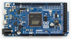
๒ Arduino Due 32bit 1 ชิ้น
๓ GY-521 IMU MPU6050 1 ชิ้น
๔ MS5611 SPI Communication 1 ชิ้น
๕ Logic Level Converter 3.3 v 1 ชิ้น
๖ Afro ESC 30Amp 4 ชิ้น
๗ มอเตอร์ UFO 4010-850KV 4 ตัว
๘ ใบพัด 10x4.5 นิ้ว 4 ใบ
๙ เฟรม quad Frame_Auto450_V2 1 ชุด
๑๐ Hobbywing UBEC 5V/6V 3A 1 ชิ้น
๑๑ สายไฟ ขั้วแบท แผ่นปริ้น รัดแบต 1 อัน
๑๒ รีโมท STORM i6S 2.4GHz 1 ชิ้น
๑๓ แบต 2200 mah 3s 30c 1 ชิ้น
๑๔ เครื่องชาจ์ท i6AC- 80W 1 ชุด
๑๕ Programmable and Documents 1 ชุด
๑๖ เสาตั้ง GPS สีดำ 1 ชิ้น
๑๗ Module RGB LED 1 ชิ้น
๑๘ อัลตราโซนิก HC-SR04 1 ชิ้น
รายละเอียดอุปกรณ์ที่ใช้
1. GPS ublox NEO 7n with compass
 Receiver type 56 Channels
Cold Start 29 s 30 s
Warm Start 28 s 28 s
Hot Start 1 s 1 s
Horizontal position accuracy Autonomous 2.5 m
SBAS 2.0 m
Max navigation update rate 10 Hz
Velocity accuracy 0.1 m/s
Heading accuracy 0.5 degrees
Dynamics ≤ 4 g
Altitude 50,000 m
 Velocity 500 m/s
2. Arduino Due 32bit
Microcontroller AT91SAM3X8E
Operating Voltage 3.3V
Flash Memory 512 KB
SRAM 96 KB (two banks: 64KB and 32KB)
Clock Speed 84 MHz
 3. GY-521 IMU MPU6050
Use the chip: MPU-6050
Power supply: 3V-5v.
Communication modes: standard IIC communication protocol.
Chip built-in 16 bit AD converter, 16 bits of data output
Gyroscope range: + 250 500 1000 2000 ° / s
Acceleration range: ± 2 ± 4 ± 8 ± 16 g
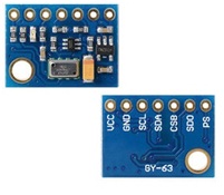 4. MS5611 GY-63 SPI Communication
Name: MS5611 module (atmospheric pressure module)
Built-in 24bit AD converter chip
High quality Immersion Gold PCB
Using the chip: MS5611
Power supply: 3V-5V (internal low dropout regulator)
Communication: Standard IIC / SPI communications protocol
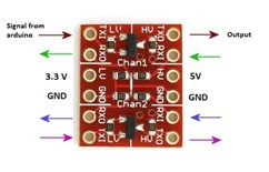 5. Logic Level Converter 3.3 v
Can be used with normal serial,
I2C, SPI, and any other digital signal
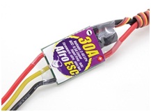 6. Afro ESC 30Amp
high efficiency,
all N-channel MOSFET design
multi-rotor specific SimonK software
Current Draw: 30A Continuous
Voltage Range: 2-4s Lipoly
BEC: 0.5A Linear
Input Freq: 1KHz
Firmware: afro_nfet.hex
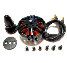
7.มอเตอร์ UFO 4010-850KV
UFO 4010 850KV Motor
Lipo 3-4 S
prop 10-13 in
FlightPower 3S 40C 5200mA batt
1255 T-Type Carbon fober prop
Frame 1020 g + batt 440 g = 1460 g
Flight time : 20 mins
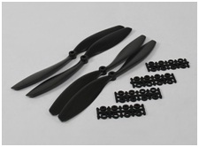 8. ใบพัด 10x4.5 นิ้ว
Propeller 10x4.5 Black (CW/CCW) (4pcs)
Prop Hole Size: 4.75mm
Prop-Adaptor Hole Size 3.0mm, 3.17mm, 4.0mm
Weight of 1 prop: 8g approximately
1 x ABS Plastic Prop CW (clockwise)
1 x ABS Plastic Prop CCW (counter - clockwise)
2 x Prop Adaptor Rings
9 เฟรม quad Frame_Auto450_V2
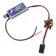
10Hobbywing UBEC 5V/6V 3A
Item Name: 3A-UBEC
Output Voltage: 5V@3A or 6V@3A (Selectable by using a jumper connector)
Continuous output current: 3 Amps
Input: 5.5V-26V (2-6S Lipo or 5-18 cells NiMH /NiCd)
Size: 43x 17 x 7mm
Weight: 11g
 11 สายไฟ ขั้วแบท แผ่นปริ้น รัดแบต
 Silicone Wire 16AWG 14 AWG
Battery Strap สายรัดแบตเตอร์รี่
สายรัดแยต กว้าง 20 ยาว 200 มิลลิเมตร
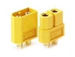
Nylon XT60 Connectors Male/Female
XT = heXTronik.
60 = 60A constant.
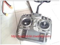 12 รีโมท STORM i6S 2.4GHz
Frequency: 2.4GHz
Modulation: DSMX
No. of Channels: 6
Model Memory: 10
Stick Mode: Mode 2 (left stick throttle)

13 แบต 2200 mah 3s 30c
Fullymax 2200 mah/3s/30c XT60 plug
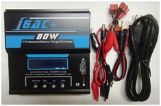 14 เครื่องชาจ์ท i6AC- 80W
Dual input: DC 11-18V, AC 100-240V
AC to DC adapter(DC 11-18V/6A)
Charge current/power: 0.1-8A/80W
Discharge current/power: 0.1-2A/10W
Current drain for balancing Lipo: 300mAh/cell
Cell count: 1-6s Lixx; 1-15s Nixx; 2-10s Pb
Dimensions: 135*145*43mm
Approx Weight: 590 g
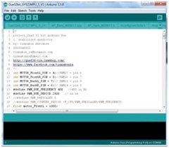
15Programmable and Documents
The open-source Arduino Software (IDE)
Arduino ide 1.5.8
Due32bit_GY521MPU_1-6_V1
 16 เสาตั้ง GPS สีดำ
GPS Holder Mount Bracket Stand
For 7N 6M M8N Neo-7N GPS
Module Black Color
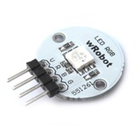 17Module RGB LED
Wrobot Full Color RGB LED Module adopt one pcs 5050 anode luminotron.
Common termination port connect with +5V, it is effective when control prot is low level.
This module can achieve effect of different color change through PWM program code.
Wrobot Full Color RGB LED Module pin definitions : (1) Vcc (2) R (3) B (4) G.
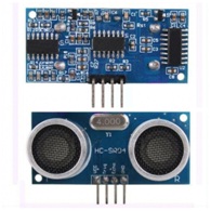
18 อัลตราโซนิก HC-SR04
PIN ที่ 1 -- 5V Supply
PIN ที่ 2 -- Trigger Pulse Input
PIN ที่ 3 -- Echo Pulse Output
PIN ที่ 4 -- GND
Working voltage: DC 5 V
Static current: 3 mA
Induction Angle: Less than 15
Detection range:2 cm to 4 m
Detecting precision: 0.3 cm + 1%
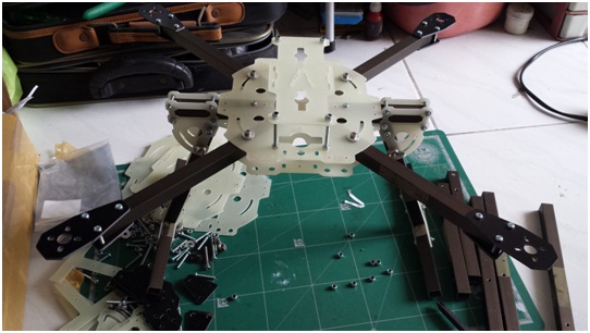
ขั้นตอนการประกอบเริ่มต้น
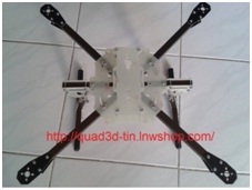
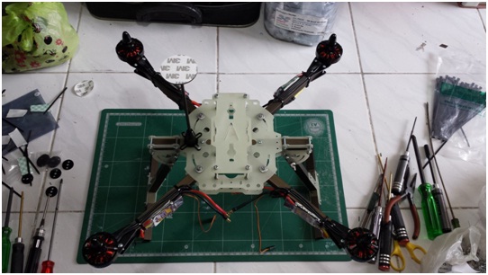
1.ทำการประกอบเฟรมเครื่องบิน 4 ใบพัด
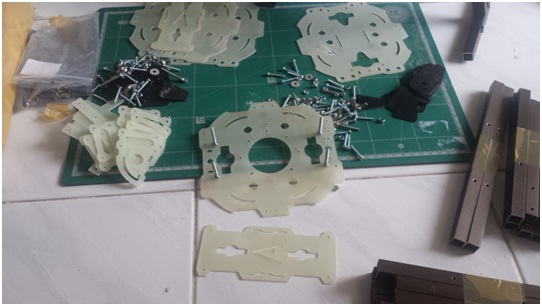
เตรียมอุปกรณ์
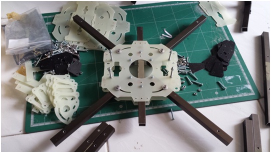
ประกอบแผ่นเฟรมหลัก แขนยึดมอเตอร์
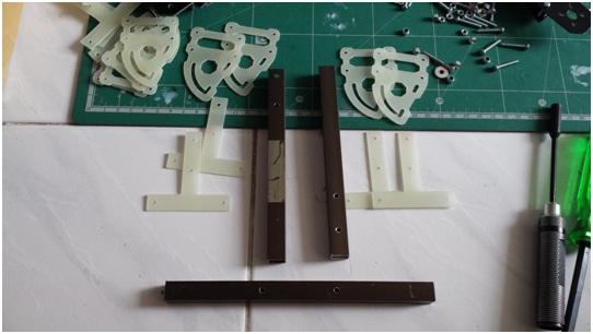
ประกอบขาตั้ง
ไขควงขันน็อตให้แน่นทุกตัว
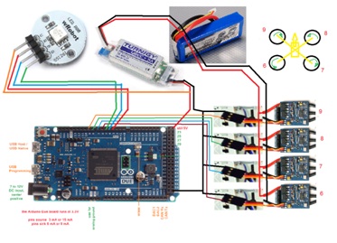
2. ทำการประกอบมอเตอร์
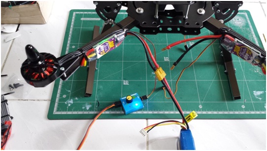
3. ทำการประกอบสปีดคอนโทรลเลอร์ (ESC)
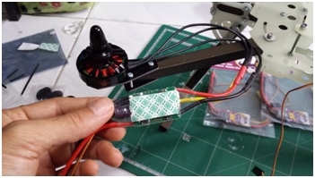
แสดงทิศทางการหมุน กับการเสียบสายไฟมอเตอร์บรัชเรด Motor Brushless
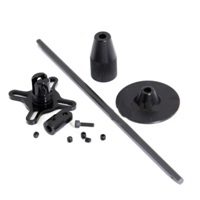
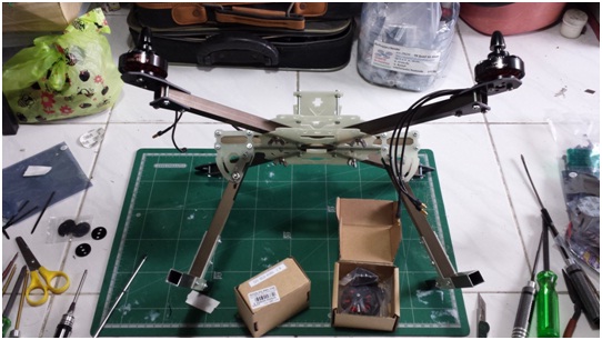
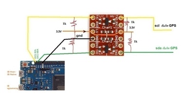
4. ทำการประกอบขาตั้ง GPS จะต้องมีสว่านมือ เจาะรู 3 mm
ประกอบมอเตอร์ สปีด เฟรม ขาตั้ง GPS ดังรูปที่แสดง
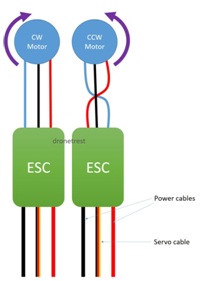
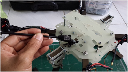
5. ตรวจสอบทิศทางหมุนของมอเตอร์ โดยใช้ Servo Tester
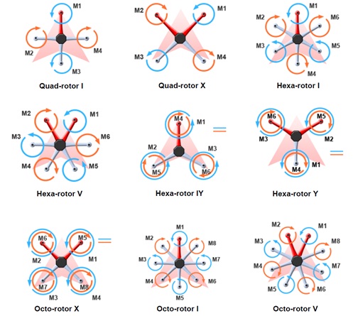
แสดงทิศทางหมุนมอเตอร์แบบต่าง ๆ ที่มา http://wiki.dji.com/en/index.php/A2_Mixer_Type_Supported
6. ติดตั้งเซนเซอร์และไมโครคอนโทรลเลอร์
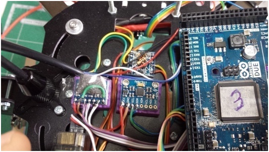

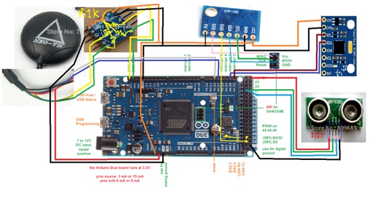
ไดอะแกรมการต่อสายไฟ
ตัว Logic Level Converter 3.3 v ใช้เพื่อแก้ปัญหา ไมโครค้างเนื่องจาก i2c เข็มทิศ hmc5883l
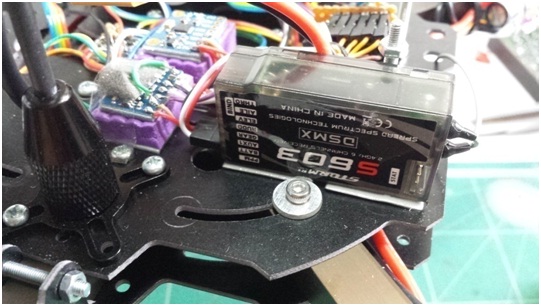
7. ติดตั้งรีซีปรีโมท ต่อสายไฟเข้าขา A8 ของ Arduino
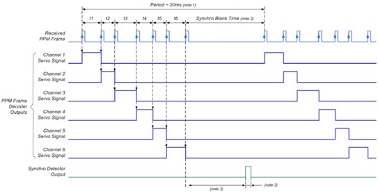
แสดงกราฟสัญญาณ PPM และ PWM
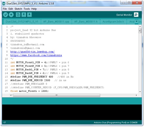
8. ทำการอับโหลดโปรแกรม Due32bit_GY521MPU_1_V1 โดยการเสียบสาย usb เข้า ProgrammingPort
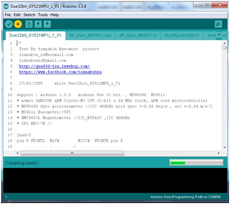
กด Upload รอสักพักหนึ่ง
9. เปิด Serial Monitor เพื่อดูค่าสถานะเซนเซอร์ต่างๆ
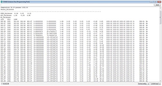
ขึ้นอยู่กับที่เราเปิด code ว่าจะปริ้นค่าอะไรมาดูบ้าง
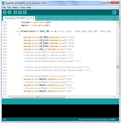
แสดงการเปิดคำสั่งปริ้นค่า Serial Monitor
10.ตรวจสอบทิศทางเซนเซอร์ ค่าความเร่งและความเร็วเชิงมุม
accelRaw[XAXIS]; accelRaw[YAXIS]; accelRaw[ZAXIS];
GyroXf*RAD_TO_DEG; GyroYf*RAD_TO_DEG; GyroZf*RAD_TO_DEG;
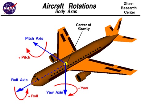
แสดงทิศทางการหมุนแกนเครื่องบิน ที่มา https://www.grc.nasa.gov
หัวข้อที่ต้องรู้ในการเขียนโปรแกรม
บอร์ด Arduino Due 32 bit ,กับ เซนเซอร์ MPU6050 - i2c , MS5611 - spi
อธิบาย Code Due32bit_GY521MPU_1-6_V1.ino
ดาวน์โหลด https://github.com/QuadTinnakon/Due32bit_GY521MPU_5_V1
1. การกำหนดความเร็วลูป
1000 Hz, 200 Hz, 100 Hz, 50 Hz, 20 Hz, 10 Hz, 5 Hz, 2 Hz, 1 Hz
1000 Hz ทำ อ่านเซนเซอร์ gyro,acc,
200 Hz ทำ ลูปคำนวณ ค่ามุม , ควบคุม PID , Filter,สั่งมอเตอร์
100 Hz ทำ อ่านเซนเซอร์ baro ความดัน
50 Hz ทำ อ่านค่ารีโมท PPM หรือ PWM
20 Hz อ่านค่า Ultrasonic , อ่านค่าเข็มทิศ, ควบคุม Position Hold
10 Hz ทำ Automatic Takeoff และ Landing
และ Chack_Command, By Remote idle-up settings 0,1,2,3
5 Hz คำนวณค่า GPS , คำนวณความสูงจาก baro
2 Hz ทำไฟกระพริบจำนวนดาวเทียมจาก GPS
1 Hz แสดงสถานะหลอดไฟ LED ทำ Accelerometers trim โดยใช้ รีโมท
2. การสร้างตัวแปรเพื่อเก็บค่า int 16 bit, long 32 bit ,uint8_t, unsigned long ,
float 32bit,
3. การอ่านค่าเซนเซอร์ gyroscope , accelerometer, magnetometer
4. การอ่านค่าบาโรเพื่อมาคำนวณค่าความสูงจากเซนเซอร์ MS5611
5. การทำตัวสังเกตเพื่อประมาณค่าความสูง ,State estimation with Kalman Filter
6. การอ่านค่าเซนเซอร์ Ultrasonic , Trigger, Echo
7. การอ่านค่าเซนเซอร์ GPS ใช้ NMEA_BINARY settings ของ MultiWii หรือ APM
8. การอ่านค่ารีโมท PWM 1-1.9 ms แบบ PPM (Pulse Position Modulation)
สายเส้นเดียว ได้ 6 CH
9. การกำหนดค่าเริ่มต้นใน setup()
- ค่าเริ่มต้นการอ่านรีโมท
- ค่าเริ่มต้นสั่งมอเตอร์
- ค่าเริ่มต้น GPS
- ค่าเริ่มต้น I2C เปลี่ยน I2C clock rate to 400kHz
- ค่าเริ่มต้นเซนเซอร์ mpu6050, HMC5883, MS5611
- ค่าเริ่มต้นอัลตร้าโซนิค
- การอ่านเซนเซอร์เริ่มต้น
- การทำคาริเบทเซนเซอร์ Gyro ให้เป็นศูนย์
- ตั้งค่าเริ่มต้นการหามุม AHRS (An attitude and heading reference
system , AHRS)
- กำหนดเวลาเริ่มต้น
10. การทำ sensor Calibration และการแปลงหน่วย rad/s , deg/s , m/s^2
11. การลดสัญญานรบกวน sensor , Moving average filter , Low pass filter
12. วิธีการหาค่ามุม AHRS, Quaternion , direction cosine matrix , Euler angles,
Rotation matrix, Body Fixed Frame, Earth-Fixed frame
13. การอ่านค่า GPS latitude and longitude , ความเร็วการเคลื่อนที่
Earth-Fixed frame
14. การควบคุมพีไอดี , P-PID , Roll, Pitch, Yaw
- คำนวณหาค่ามุมรีโมท
- การดิฟหาความเร็วจากมุมรีโมท
- การคำนวณค่า error
- การคำนวณกฏการควบคุมมุมและ Rate Gyro
- การป้องกันค่าเกิน Saturation
15. การควบคุมความสูงAltitude ใช้ State feedback control หรือ PIDA
16. เทคนิคการจูนค่า Gain ที่ใช้ควบคุม
17. เงื่อนไขการทำ Automatic Takeoff และ Landing
18. การควบคุมต่ำแหน่ง GPS ใช้ PID control
19. การทำ Motor mixing theory, Quad +,x
20. การสั่ง PWM 1-1.9 ms, 400 Hz ให้มอเตอร์หมุน
21. การทำ Electronic Speed Controllers Calibration 1000 - 1850 us
22. การทำ Accelerometers trim โดยใช้ รีโมท
23. การทำ Calibration sensor Accelerometer หาค่า Max , Min
24. การทำ Calibration sensor Magnetometer หาค่า Max , Min
25. การกำหนดค่าเข้าโหมดบิน ต่าง ๆ Stabilizer, Altitude Hold, Position Hold, RTH,
Automatic
26. การทำ ARM and DISARM มอเตอร์หมุนและไม่หมุน
27. อื่น ๆ .....
- การตั้งค่ารีโมทวิทยุ 2.4 GHz
- การชาร์จแบตเตอรี่ลิโพ 4.2 โวลต์ Lithium Polymer
-----------------------------------------------------
ตัวอย่างโปรแกรมที่เขียน
(Quadrotor Autopilot / Flight Controllers)
ดาวโหลด Code ได้ที่ https://github.com/QuadTinnakon/Due32bit_GY521MPU_5_V1


